A two-level hardware and software failure handling mechanism.
When disk drives are used, they undergo repeated read and write operations from the sector space.
However, various failures occur during their operation, the most common of which is the appearance of unreadable sectors,
so-called "bad sectors".
For this case, the drive's control firmware includes a mechanism for logically replacing such sectors with sectors from the drive's reserve
sector space.
This substitution is not done on the fly and is practically unnoticeable for the operating system.
However, the size of the reserve area is limited, and with prolonged use of drives, this area may become exhausted.
This can lead to the device's control firmware encountering an unresolvable problem, and the drive becomes unable to respond to operating system requests.
Depending on the operating system version, this manifests itself either as a freeze in the I/O subsystem or as a drive responding to any commands.
Experiments have shown that temporarily interrupting the 5-volt power supply is sufficient to bring the drive out of this state.
The drive will then perform a so-called recalibration and return to its original state.
The program provides two options for manipulating the 5-volt supply to the drive:
- Manual switching on/off by a 5-volt power supply program command;
- Using the LCUS-1 Relay Module;
Manual switching on/off by command from the five-volt power supply program.
You can interrupt power to the drive by disconnecting the drive's power connector, but this can damage the connector or cause it to wear out prematurely.
Therefore, the best solution is to install a regular switch in the red wire of the power connector, Fig. 215b.
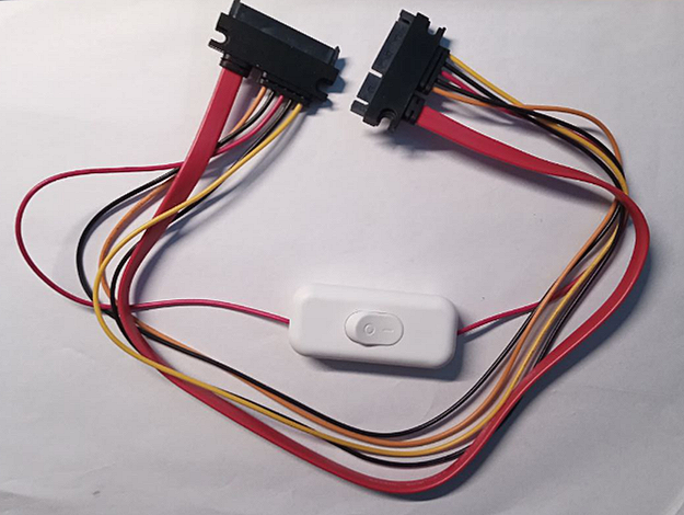 Fig. 215b. A normal switch on the red wire of the connecting cable.
If a drive's readiness is lost, the program prompts the user to briefly interrupt power to the affected drive:
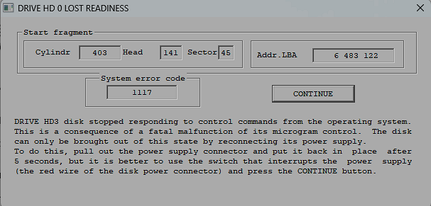 Fig. 215a. Request to turn off power for a short time.
After which it reads the obviously readable sector and continues working.
Application of the LCUS-1 relay module.
The process of processing a failure and performing the recalibration procedure for the affected drive takes several tens of seconds.
Therefore, with a large number of such failures, a situation may arise where operating with a large number of failures becomes too tedious.
Currently, on the global microelectronics market, you can purchase a single-channel relay module LCUS-1 at a very low price.
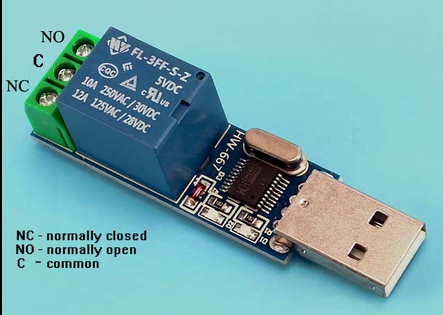 Fig. 216d. Single-channel Relay Module LCUS-1.
Its brief description:
- Country of origin: Mainland China;
- CH340 USB control chip;
- Built-in LED indicators for power and relay status;
- Switching lifespan: 100,000 times;
- PCB size: 49.6 (mm) x 16 (mm);
USB switch, default baud rate: 9600
- USB relay communication protocol:
- The first byte is the startup logo (0 xA0 by default);
- The second byte is the switch address code (0 x01 by default, identifies the first channel);
- The third byte is the operation data (0 x00 for "off", 0 x01 for "on");
- The fourth byte is the checksum;
- It does not require installation of additional drivers; its maintenance is built into the Windows operating system.
To do this, disconnect the red power supply wire and connect it to the normally closed contacts NC and C, Fig. 216d.
When launched, the FomsoftDataRecovery program checks for the presence of a connected LCUS-1 Relay Module
and can use it to automatically handle readiness loss events on the affected drive.
 Рис. 215c. USB relay on the red wire of the connecting cable.
|
